Of course! Drawing graphs with Python and Graphviz is a powerful way to visualize data structures, algorithms, workflows, and more. It involves two main steps:

- Define the Graph Structure: In your Python code, you create a graph object and add nodes and edges to it.
- Render the Graph: You pass this Python object to the Graphviz library, which then generates a DOT file and calls the Graphviz executables (
dot,neato, etc.) to render it into an image file (like PNG, SVG, or PDF).
Here's a complete guide, from installation to creating complex graphs.
Step 1: Installation
You need to install two things: the Python package and the Graphviz software itself.
A. Install the Python Package
Use pip to install the graphviz library, which is a Python interface to Graphviz.
pip install graphviz
B. Install the Graphviz Software
The Python package is just a wrapper. You still need the actual Graphviz executables installed on your system.

- On macOS (using Homebrew):
brew install graphviz
- On Ubuntu/Debian:
sudo apt-get update
sudo apt-get install graphviz
- On Windows:
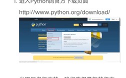
- Download the installer from the official Graphviz download page.
- Run the installer. Crucially, during installation, make sure to select the option to "Add Graphviz to the system PATH for all users". If you miss this step, the Python library won't be able to find the executables.
- After installation, you may need to restart your terminal or IDE.
To verify the installation, open a terminal or command prompt and run:
dot -V
This should print the version of the dot executable. If you get an error, the system PATH is not set up correctly.
Step 2: A Simple Example (The Basics)
Let's start by creating a simple directed graph with two nodes and one edge.
from graphviz import Digraph
# 1. Create a Digraph object
# 'digraph' means it's a directed graph (arrows on edges)
dot = Digraph(comment='The Round Table')
# 2. Add nodes
# You can give nodes a name and a label
dot.node('A', 'King Arthur')
dot.node('B', 'Sir Bedevere')
dot.node('C', 'Sir Lancelot')
# 3. Add edges
# Edges are defined by the name of the source and target nodes
dot.edges(['AB', 'AC', 'BA'])
# 4. Render the graph to a file
# This will create a 'round_table.gv' file and a 'round_table.png' image
dot.render('round_table', view=True)
# The 'view=True' argument automatically opens the image file with your default viewer.
What this code does:

Digraph(...): Creates a new directed graph object.dot.node(name, label): Adds a node. Thenameis used for internal graph structure (e.g., for connecting edges), and thelabelis what is displayed on the visual.dot.edges([...]): A convenient way to add multiple edges from a list of pairs.dot.render(filename, view=True): This is the key command.- It generates a DOT file (e.g.,
round_table.gv). - It calls the
dotexecutable to convert this file into an image (e.g.,round_table.png). view=Trueopens the resulting image.
- It generates a DOT file (e.g.,
Step 3: Graph Attributes (Styling Your Graph)
Graphs can be customized extensively. You can set attributes for the graph itself, for nodes, and for edges.
from graphviz import Digraph
dot = Digraph('Options', format='png') # format='png' directly creates a PNG file
# Set global graph attributes
dot.attr(rankdir='LR') # LR = Left to Right, TB = Top to Bottom
dot.attr('node', shape='box', style='rounded,filled', fillcolor='lightblue')
# Add nodes with specific attributes
dot.node('start', 'Start Process', shape='ellipse', fillcolor='green')
dot.node('process1', 'Process 1')
dot.node('decision', 'Decision?', shape='diamond', fillcolor='gold')
dot.node('process2', 'Process 2')
dot.node('end', 'End Process', shape='ellipse', fillcolor='red')
# Add edges with specific attributes
dot.edge('start', 'process1', label='init')
dot.edge('process1', 'decision', label='done')
dot.edge('decision', 'process2', label='yes', color='green')
dot.edge('decision', 'end', label='no', color='red')
dot.edge('process2', 'end', label='finish')
# Render the graph
dot.render('flowchart', view=True)
Common Attributes:
- Graph:
rankdir(layout direction),splines(how edges are drawn). - Node:
shape(box,ellipse,diamond,circle),style(filled,rounded),color,fillcolor,fontname. - Edge:
label,color,fontsize,arrowhead(normal,vee,dot).
Step 4: Different Graph Types
The graphviz library supports several types of graphs.
A. Undirected Graph (Graph)
Use Graph for graphs where edges have no direction (use simple lines, not arrows).
from graphviz import Graph
# Create an undirected graph
undot = Graph('Undirected Graph', format='svg')
undot.node('A')
undot.node('B')
undot.node('C')
undot.edges(['AB', 'BC', 'CA'])
undot.render('undirected_graph', view=True)
B. Other Layout Engines (Graph, Digraph)
The dot engine is great for hierarchical (directed) graphs. For other layouts, you can use different engines like neato (for undirected graphs, force-based), fdp (another force-directed), circo (circular), or twopi (radial).
You specify the engine with the engine parameter.
from graphviz import Graph
# Use the 'neato' engine for a force-directed layout
neato_graph = Graph('Neato Layout', engine='neato')
# A more complex structure looks better with neato
neato_graph.node('A')
neato_graph.node('B')
neato_graph.node('C')
neato_graph.node('D')
neato_graph.node('E')
neato_graph.edges(['AB', 'AC', 'BD', 'CD', 'DE'])
neato_graph.render('neato_graph', view=True)
Step 5: Advanced Features
A. Subgraphs (subgraph)
You can group nodes into subgraphs, which is useful for clustering or controlling the layout.
from graphviz import Digraph
dot = Digraph('Clustered Graph')
# Define the main graph
with dot.subgraph(name='cluster_0') as c:
    c.attr(label='Process A')
    c.node('a1', 'Start A')
    c.node('a2', 'Middle A')
    c.node('a3', 'End A')
    c.edges(['a1a2', 'a2a3'])
with dot.subgraph(name='cluster_1') as c:
    c.attr(label='Process B', style='filled', color='lightgrey')
    c.node('b1', 'Start B')
    c.node('b2', 'End B')
    c.edges(['b1b2'])
# Edges between subgraphs
dot.edge('a3', 'b1', constraint='false') # constraint='false' prevents layout engine from trying to keep them ordered
dot.render('subgraph_example', view=True)
B. Using Objects as Node Names
You can use any hashable object (like a class instance) as a node name, which is very useful for visualizing complex data structures.
class Person:
    def __init__(self, name, role):
        self.name = name
        self.role = role
    def __repr__(self):
        return f"Person({self.name}, {self.role})"
# Create graph objects
arthur = Person('Arthur', 'King')
lancelot = Person('Lancelot', 'Knight')
guinevere = Person('Guinevere', 'Queen')
dot = Digraph('Character Relationships')
# Add nodes using the objects directly
dot.node(arthur, label=f'<<B>{arthur.name}</B><BR/><FONT POINT-SIZE="10">{arthur.role}</FONT>>')
dot.node(lancelot, label=f'<<B>{lancelot.name}</B><BR/><FONT POINT-SIZE="10">{lancelot.role}</FONT>>')
dot.node(guinevere, label=f'